Last Friday we had the PDR with the reviewers, who are professors, alumni and friends at
UCLA. They provided many insights to the three software components of the project, especially the controls part.
From this review we all got a better sense of the progress each team made. Overall, they suggested that we
should get some of the details sorted and work more on the simulations before actually flying the drones. The
simulation part, given its complexity, might play a much more important role in the project in the
future.
The next steps for the software team are digesting the advice we received from PDR, adjusting some of
the designs, and getting to design some APIs that interact with different parts of the project.
Over the past two weeks, our Mechanical Airframe team has been heavily involved with making
adjustments to the octagonal frame and docking mechanism in preparation for the Preliminary Design Review which
was held on 10/30.
After analyzing the difficulty in securely attaching a large Apriltag to the center of the
octagonal frame, most likely via some fishing wire, we decided to rethink our design and go with a more
conventional octocopter-like frame which consists of spokes protruding from a central body. This way, the
Apriltag will have a solid surface to be attached to, and the payload will also be more easily secured. They
will attach to the frame's central plate, from which the 8 boom arms will extend. These arms will just be single
2.11 cm diameter carbon fiber tubes, as opposed to twin rods, since torsion is no longer a significant concern
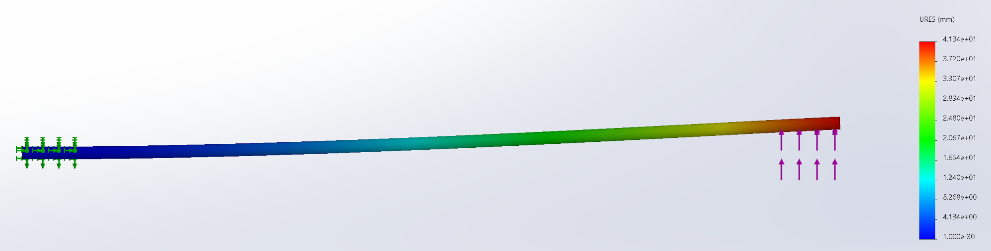
with the new frame design. A free surface simulation was performed, due to it being more computationally
efficient than a complete body simulation, on the carbon fiber tube to validate its strength under full throttle
of the drone. The results of the simulation can be seen below and it is evident the selected tube is sufficient
as the deflection at the end of the tube is insignificant. We saw 4.13 cm of deflection at the end of a 115 cm
boom.
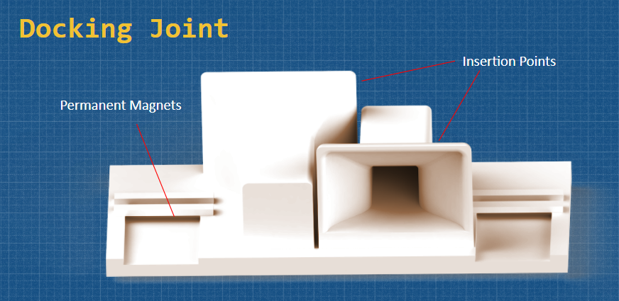
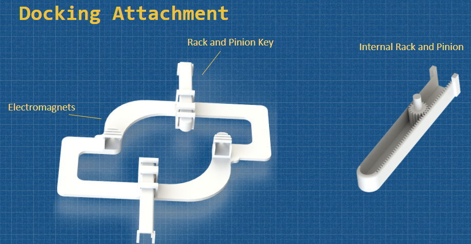
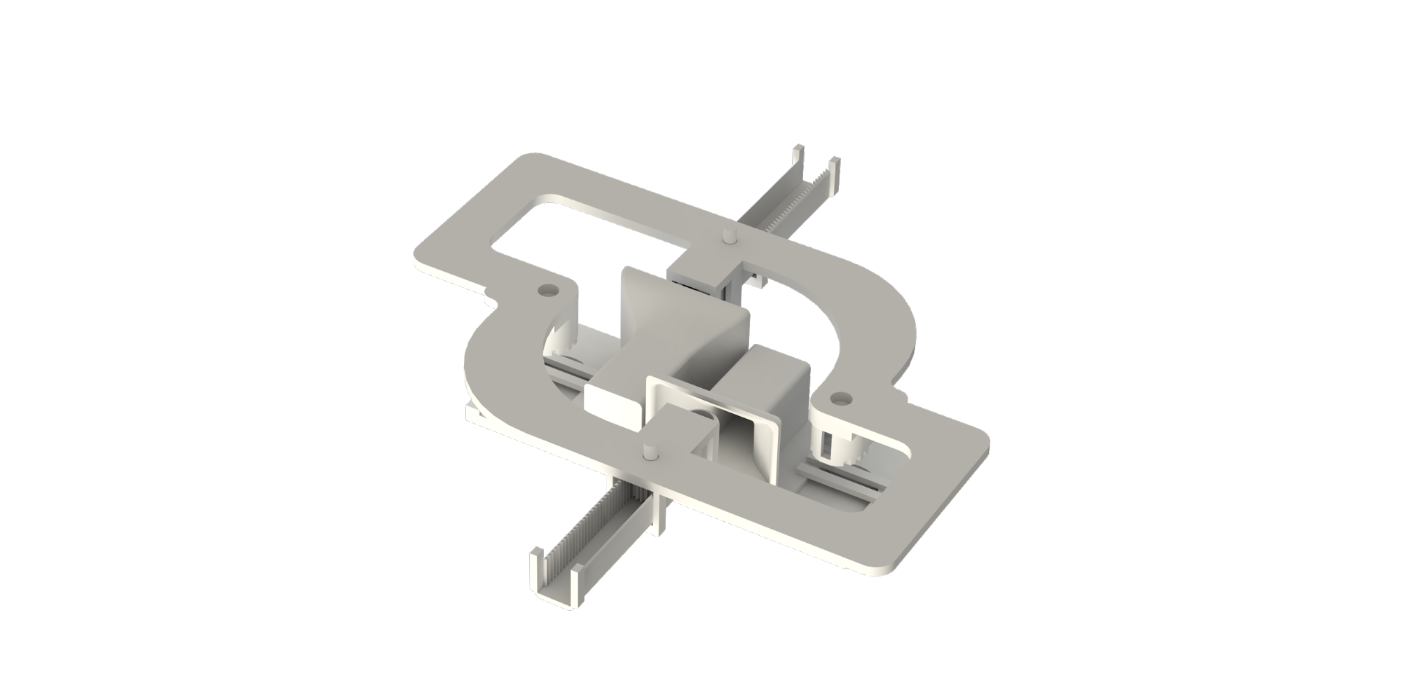
The next modification we made was to the docking mechanism.
The revised docking adapter boasts a 3D printed body that can be attached to the drone. It has two slots for
electromagnets of opposite polarities such that the orientation can be locked in with permanent magnets on the
docking joint which is attached to the frame. These electromagnets will be powered during the docking stage to
properly align as well as during undocking in order to push away from the frame by reversing their polarity. The
next important aspect of the docking adapter is an internal rack and pinion key that is controlled by motors.
These keys will slide into the docking joint insertion points, which are flared to account for any translational
discrepancies, in order to securely attach to the frame. As a result, the docking mechanism has been designed to
be as robust and simplistic as possible.
Overall, these design changes led up to the
Preliminary Design Review where we got some great feedback and insight on our design. For instance, it was
recommended that we look into stronger electromagnets so that the precision docking can be aligned from further
away. It was also suggested that we open the back of the insertion points on the docking joint so that any wind
gusts will have a reduced impact. Lastly, it was reiterated that we talk about the canted motor design with
Brett Lopez, and discuss the best way to implement that feature.
These results are based upon work supported by the NASA Aeronautics Research Mission
Directorate under award number 80NSSC20K1452. This material is based upon a proposal tentatively selected by
NASA for a grant award of $10,811, subject to successful crowdfunding. Any opinions, findings, and conclusions
or recommendations expressed in this material are those of the authors and do not necessarily reflect the views
of NASA.
 Join
Calendar
Officers
Gallery
Tools
Join
Calendar
Officers
Gallery
Tools