These past few weeks, the Airframe team had been heavily focused on developing the docking
mechanism and docking joint that was illustrated in the latest blog post.
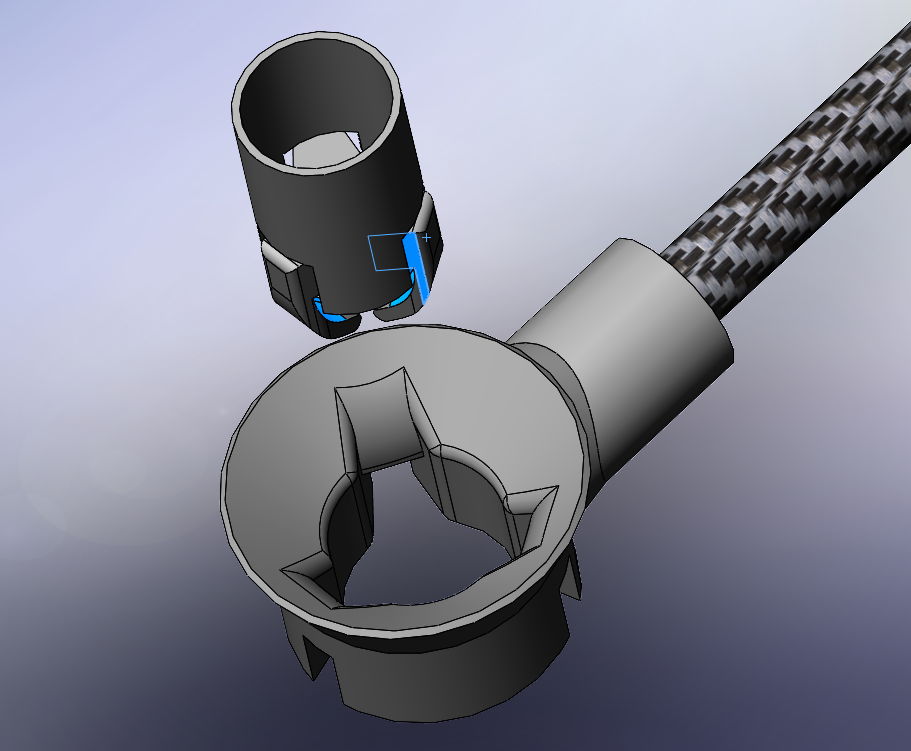
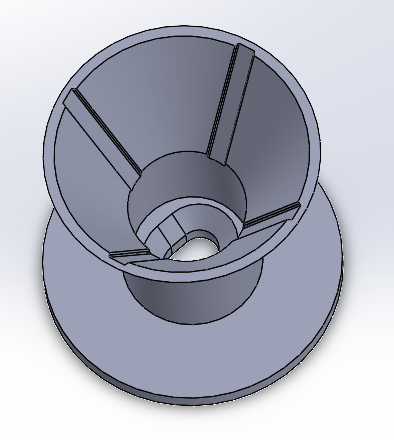
Specifically, our team worked on
designing a fully functional docking joint that is to be attached to the newly purchased square carbon fiber
tubes. The docking joint contains guiding channels that the flaps on the mechanism can follow for accurate
docking. At the bottom of the joint, through an egg-shaped hole, is a piece of conductive foil that completes a
circuit on the docking mechanism, letting our software know that the flaps are in the proper position to be
extended. The joint will also have an attachable platform that the Apriltag can be mounted to for drone
identification.
For
preliminary testing, however, our docking mechanism is merely a cylindrical column that can be attached to the
drone and fit through the egg-shaped hole at the bottom of the joint for completing the circuit. It also
contains small extrusions that mimic the form factor of the flaps in order to provide a more accurate testing
environment.
The purpose of these docking components is to allow our Docking team to simulate drone docking with the
physical hardware, while we continue to flesh out the design of the docking mechanism, specifically, the flaps
and other mechanical attachments. This is what our main focus will be moving into the next few weeks.
We'd
also like to officially welcome Daniel Paul to the USRC Airframe team as he begins work on our drone camera
mount and Apriltag mounts! And another (belated) warm welcome to Daniel Lin who joined a few weeks ago and is
helping out with the docking mechanism!
As always, thanks for following us on our journey and stay tuned for
the next blog post!
On the software side, we've had many recent successes and developments since our last
update, bringing us closer to our final goal of having an operational system.
Firstly, we've finally begun
integrating the 3 software subteams. Chirag has had great success combining the docking and controls simulation,
with the goal of having one drone be able to dock next to the leader and transition into the collaborative
controls code. Puneet has been helping Yuchen research and develop the communications code in attempting to
integrate communications with controls.
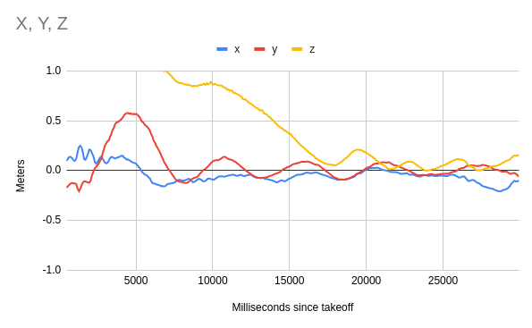
Moving on to docking, the team has solved the issue that has been
slowing down testing that we mentioned in our last post. The PID controller on-board the drone that handles
normal flight is sensitive to noise, which comes from vibrations, and after remounting everything on the drone,
balancing the propellers, and tweaking some software parameters related to the gyroscope, the drone is flying
better than ever. This has improved the performance of our docking software, allowing the drone to be even more
precise when attempting to land on a target. The following graph shows just how well the drone is able to detect
its position relative to the target and adjust its flight to approach it. Each of the 3 lines shows how far the
drone is from the target in that dimension.
This
success was enough to begin attempting two-stage docking, which we have so far only tested in simulation. After
some trial and error with PID values in our image recognition loop, we successfully pulled off two-stage
docking:
Now that we've validated that everything we've done in simulation works
on board a physical drone, the primary goal is to continue to fine-tune the PID controller to enable the drone
to be precise enough to engage the docking mechanism that will be provided by the airframe team.
The controls
team has also reached significant milestones. The canted motor testing (in which the motors are angled by 10°
toward the center of the drone) as introduced in the last blog post was successful, making it much easier for
drones to control their yaw when rigidly attached together. This will help tremendously for the upcoming 4-drone
test, in which the objective will be to fly 4 rigidly-attached drones together, an upgrade from the current
2-drone tests. To accomplish this 4-drone test, we've ordered several more drones, as well as enough carbon
fiber for the airframe team to construct a way to attach 4 drones together. All of this will be sent to the
controls team for testing in the coming weeks.
Another important development has been the ability for the
system to designate a new leader drone. In its current form, AVIATA has 1 leader drone, with the rest of the
drones being “followers” who receive attitude commands from the leader. In the following video, Ryan was able to
successfully change which drone was the leader and which one was the follower, which is a critical component to
being able to have drones swap in and out of the system. You can notice when the switch happens with a small dip
in altitude.
Finally, communications has continued to research the best method to
bring mesh networking to the current implementation of the controls code, which uses ROS2. One of the promising
options is to have the communications code intercept ROS2 messages and redirect them to the mesh networking
interface, which would streamline the process. This option is easier than trying to create custom ROS2
middleware, which has proved to be a challenge.
These results are based upon work supported by the NASA Aeronautics Research Mission
Directorate under award number 80NSSC20K1452. This material is based upon a proposal tentatively selected by
NASA for a grant award of $10,811, subject to successful crowdfunding. Any opinions, findings, and conclusions
or recommendations expressed in this material are those of the authors and do not necessarily reflect the views
of NASA.
 Join
Calendar
Officers
Gallery
Tools
Join
Calendar
Officers
Gallery
Tools